
This is a list of topics I had to commit to memory when studying on HamTestOnline.com for my Extra Amateur Radio License.
Bandwidth
- A signals bandwidth is determined 26 dB below a signals mean power level.
| Freq/Mod | Bandwidth |
|---|---|
| 13 Words Per Minute CW | 52 Hz |
| 25 Words Per Minute CW | 100 Hz |
| HF Packet (170Hz Shift@300 Baud) | 504 Hz or ~0.5 kHz |
| VHF Packet (1000Hz Shift@1200 Baud) | 2400 Hz |
| UHF Packet (4800Hz Shift@9200 Baud) | 15.36 kHz |
- To reduce bandwidth PSK31 use sinusoidal pulses rather than square pulses.
- Caused by excessively short rise and fall times, key clicks, are emissions outside the necessary bandwidth of CW. It can be reduce by increasing keying waveform rise and falls times.
- Amateur stations are limited to 1W EIRP on 2200M band and 5W EIRP on 630M band.
- Antennas used on these band must not exceed 60M above ground level.
- RTTY, data, phone and image emissions are permitted in all portions of both bands.
Antenna Gain
- Formula: dBd=dBi−2.15 dB
Antenna Fields
- Near field is the region close to the antenna where the pattern is chaotic.
- Far field is the region where the pattern looks the same regardless of distance from antenna.
Antenna Beamwidth
In a radio antenna pattern, the half power beam width is the angle between the half-power (-3 dB) points of the main lobe.
Antennas:
Parabolic Antenna
- Saucer like antenna with dipole at the focus point.
- Doubling the diameter or frequency increases the gain by a factor of 4, so 6dB.
Basic Wire
- Random Wire: Simplest antenna. Random length suspended above the ground, can be straight but not necessarily. Sometimes thrown into the trees.
- Long Wire: This is a random wire that is least 1/4 wavelength long. Some say it should be at least a wavelength. Shares characteristics with the Beverage antenna; as the antenna gets longer it becomes more directional along its axis.
Dipoles
- Off center fed dipoles (OCFD): A multiband dipole fed typically a third from one end. May require an impedance matching device (4:1 balun).
- G5RV Antenna: A multiband dipole that can be used across the entire HF spectrum (with a tuner).Fed by coaxial, connected to a balun to an impedance matching section of window line.
- Zepp antenna: An end fed dipole. Was used on the Zeppelin airship.
- Extended Double Zepp antenna: Center fed dipole with 5/8 wavelengths on each side instead of 1/4.
Mobile antennas
- As part of an HF mobile antenna, a loading coil used to cancel capacitive reactance.
- SWR bandwidth is decreased when one or more loading coils are used to resonate an electrically short antenna
- Using a high ratio of reactance to resistance (high Q loading) in the center of the vertical antenna should minimize losses.
Amateur Satellite Authorized Frequencies
L Band and S Band, refer to 23 and 13 centimeters, respectively
| Frequency | Band |
|---|---|
| HF | 40, 20, 17, 15, 12, and 10 meters |
| VHF | 2 meters |
| UHF | 70, 23, and 13 cm |
Impedance of Open and Shorted Transmission Lines
1/2 Wavelength:
- Shorted at far end = very low impedance
- Open at far end = very high impedance
1/4 Wavelength:
- Shorted at far end = very high impedance
- Open at far end = very low impedance
1/8 Wavelength: When < 1/4 shorted acts as inductor and open acts as capacitor
- Shorted at far end = inductive reactance
- Open at far end = Capacitive reactance
Antenna Feed-Point Impedance
- When antenna is resonant, the impedance is purely resistive.
- Moving away from resonant frequency decreases impedance and radiation resistance (whether lower or higher frequency).
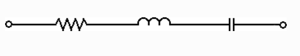
- As the frequency is lowered to the point is too short for the frequency you are using, it acts like a capacitor and resistor in series.
- As the frequency is raised to the point is too long for the frequency you are using, it acts like a inductor and resistor in series.
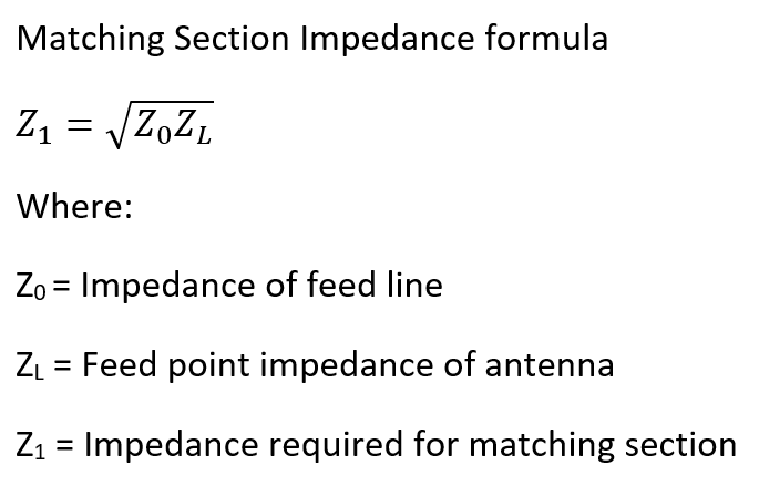
Impedance Matching
Q-section
- 1/4 wavelength piece of mismatched feed line inserted between the regular feed line and the antenna feed point.
- This calculation is not on the exam but here's the formula:
Stub Match
- Feed line connected in parallel with the feed line at or near the feed point. Allows matching a wide range of impedances by varying length of stub, how close to the feed point it is connected and whether it's open or shorted.
- Universal stub matching system is a system that allows one to slide the attachment for easy adjustment.
Gamma Match
- Connects feed lines to lower impedance antennas.
- Used to connect an unbalanced feed line (coaxial) to a Yagi. The outer shield is connected to the driven element and the inner is connected a fraction of a wavelength to one side of center. Sometimes the inner wire is connected through a capacitor to cancel out the inductive reactance brought on by the gamma match.
- Using a gamma match allows driven element to not be insulated from the boom.
- Gamma match is also used as a Shunt-feed antenna. This converts a grounded tower into a vertical antenna.
Delta Match
- Connects feed lines to lower impedance antennas.
- Used to connect a balanced feed line (ladder line) to a Yagi. The two conductors are connected to either side of the driven element a fraction of a wavelength from center.
High-pass Filter
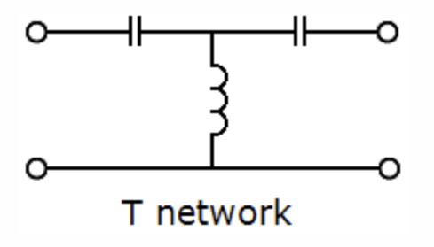
Note: Series capacitors pass high freq's while inductor shunt shorts out low freq's.
Low-pass Filter
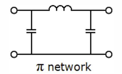
Note: Inductor pass high freq's while capacitor shunts shorts out high freq's.
Smith Chart
A common use of this chart is to help calculate the length and position of an impedance matching stub.
- Straight line is resistance axis
- Outer circle is reactance axis
- Other inner circles represent resistances
- Arcs are reactance where left is zero to infinite capacitive reactance and right is zero to infinite inductance reactance.
- Alternate labeling of reactance axis calibrate in fractions of transmission line electrical wavelength.
- Prime center = resistance of one and reactance of zero.
- The formal process of normalizing impedances on the Smith chart is … reassigning impedance values with regard to the prime center
Certification of External RF Power Amplifiers
- 43dB is the permitted mean power of any spurious emission relative to the mean power of the fundamental emission from a station transmitter or external RF amplifier and transmitting on a frequency below 30Mhz
Logic Circuits
- NOT Gate: One input and outputs the opposite of the input.
- AND Gate: Two inputs. Output is true when both inputs are true else output is false.
- OR Gate: Two inputs. Output is false when both inputs are false, else output is true.
- XOR Gate: Two inputs. Output is true when ONLY one input is true, else output is false.
- NAND Gate: Two inputs. Not the result of an AND gate. Output is true when one or both inputs are false else output is false.
- NOR Gate: Two inputs. Not the result of an OR gate. Output is true when both inputs are false, else output is true.
- XNOR Gate: Two inputs. Not the result of an XOR gate. Output is true when both are false or true, else output is false.
Note: positive logic circuits represent true with a high voltage. Negative logic circuits do the opposite.
Geomagnetic Storms
- Solar flares are categorized (from weakest to strongest) into classes A, B, C, M, or X
- NOAA Geomagnetic storm G-scale is derived directly from K-index going from minor to extreme geomagnetic storms (G-1 --> G-5).
- Strong southward component (negative BZ) is correlated to geomagnetic storms.
- 304A solar parameter measure UV emissions at 304 angstroms, correlated to the solar flux index
Propagation
- Radio horizon tends to be greater than geometric horizon, because signals travel along the curvature of the earth and density of the atmosphere decreases with altitude causing low angle signals to be refracted back to earthen.
- Regarding VHF/UHF, radio horizon exceeds geometric horizon by ~15%. Also, as frequency increases, refraction decreases making the radio horizon shorter.
- Tropospheric propagation of microwave signals are typically 100 to 300 miles.
- Transequatorial propagation maximum range is about 5000 miles.
- Sporadic E propagation range is 500 to 1400 miles and is most common around summer solstice with a smaller peak during winter solstice.
- Meteor scatter propagation is the reflection of radio waves off small cylinders of ionized gases formed when small meteors burn up in the E layer of the ionosphere. Frequency ranges suited include 28 MHz - 148 MHz, where 6 meters is the best band for this propagation in the early morning, especially during meteor showers.
- Aurora propagation scatter HF and VHF signals via charged particles in the E layer. Signals tend to flutter and distort so CW is the best mode. During communications, both stations should be pointed to the north.
- Earth-Moon Earth (EME) propagation range is about 12,000 miles as long as moon is visible by both stations and requires high power and high gain antennas. Libration is the perceived oscillation of the moon due to its elliptical orbit, inclination of its rotation and earth's rotation. Libration fading is the fluttering, irregular fading of EME signals due to these motions and irregular surface of the moon.
RLC Circuits
Series RLC Circuit
- At resonance, impedance is at minimum and current through the circuit is at a maximum.
- At resonance, the impedance of the circuit is just resistance.
Parallel RLC Circuit
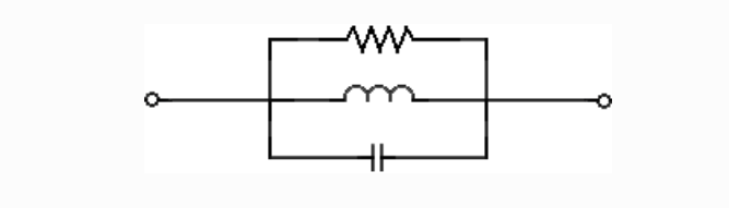
- At resonance, impedance is at a maximum and current through the circuit is at a minimum.
- At resonance, the impedance of the circuit is just resistance.
Interference
- The preselector in a receiver is used to increase rejection of signals outside the desired band.
Intermodulation
- Intermodulation products in a linear power amplifier may transmit spurious signals.
- Odd-order products of two signals in the band of interest are also likely to be within the band.
- Odd-order rather than even-order intermodulation distortion products are of a concern in linear amplifiers cause they are relatively close in frequency to the desired signal.
- Nonlinear circuits or devices cause intermodulation in a an electric circuit.
- When an excessive amount of signal energy reaches a mixer circuit, spurious mixer products are generated.
- Excessive transmit audio levels cause overmodulation of AFSK signals.
Oscillator
- A capacitive divider provides positive feedback for a Colpitts oscillator.
- A tapped coil provides positive feedback for a Hartley oscillator.
- A quartz crystal provides positive feedback for a Pierce oscillator.
- Colpits and Hartley are commonly used in VFO's.
- Ensure a crystal oscillator produces desired frequency, use manufacturer specified parallel capacitance.
- Use NP0 capacitors to reduce thermal drift of oscillator.
- Reciprocal mixing is local oscillator phase noise mixing with adjacent strong signals to create interference to desired signals
- Microphonic are changes in oscillator frequency due to mechanical vibration. It can be reduce by mechanically isolate the oscillator circuitry from its enclosure.
Calculations
Time Constant
T = R*C
First calculate total Resistance (ohms) and Capacitance (farads), then plug them into the above formula.
Effective Radiated Power
ERP = Pt * 10 (dBd/10)
EIRP = Pt * 10 (dBi/10)
First calculate the total loss and subtract it from the total gain.
Resonant Frequency of an RLC Circuit
Where:
| L = Inductance in Henries C = Capacitance in farads
|
*When L=µH and C=pF substitute 1000 for 1 in the numerator.
Sample Problem #1:
What is the resonant frequency of a series RLC circuit if R is 22 ohms, L is 50 microhenries and C is 40 picofarads?
Fr = 1000/2π * SQRT(50*40) = 3.56MHz
Sample Problem #2:
What is the resonant frequency of an RLC circuit if R is 33 ohms, L is 50 microhenries and C is 10 picofarads?
Fr = 1000/2π * SQRT(50*10) = 7.12MHz
Quality Factor
Is the measure of the quality of a resonant system. High Q has a narrower peak or dip in frequency response function.
High Q circuit requires high-grade capacitors and inductors, with low losses to internal resistance.
Increasing the Q in a series resonant circuit INCREASES INTERNAL VOLTAGES.
Series RLC: Q = reactance / resistance
Parallel RLC: Q = resistance / reactance
When performing this calculation, you can use inductive or capacitive reactance, because at resonant frequency inductive and captative reactances are equal.
Half Power Bandwidth
Half Power Bandwidth is like Q. Sometimes referred to as “the bandwidth of the circuit’s frequency response.”
It is the width of the frequency range in which the series circuit stops, or parallel passes, at least half the power as at the resonant frequency.
A higher Q always means a sharper response, and thus a narrower bandwidth.
Half Power Bandwidth = fR / Q
Sample Problem #1:
What is the half-power bandwidth of a resonant circuit that has a resonant frequency of 3.7 MHz and a Q of 118?
HPB = 3.7/118 = 0.03135 MHz = 31.4 kHz
Sample Problem #2:
What is the half-power bandwidth of a resonant circuit that has a resonant frequency of 7.1 MHz and a Q of 150?
HPB = 7.1/150 = 0.04733 MHz = 47.3 kHz
Operational Amplifier (Op Amp)
Given the following figure:

The magnitude of the voltage amplification (absolute voltage gain):
Av = RF/R1
Output Voltage:
Vout = -Vin * Av
Sample Problem #1:
What magnitude of voltage gain can be expected from the circuit above when R1 is 10 ohms and RF is 470 ohms?
Av = 470/10 = 47
Sample Problem #2:
What will be the output voltage of the above circuit if R1 is 1000 ohms, RF is 10000, and 0.23 volts DC is applied to the input.
Vout = -0.23 * 10000/1000 = -2.3V
Frequency Modulation
Deviation Ratio of FM signal
Dmax / Mmax
| Where: | Dmax = Maximum Carrier Frequency Deviation Mmax = Maximum Modulating Frequency |
For Narrow band FM
Deviation Ratio = Dmax / Mmax = 5kHz/3kHz = 1.67kHz
Modulating Index for FM
Frequency Deviation / Modulating Frequency
The highest modulation index permitted at the highest modulation frequency for angle modulation below 29.0 MHz is 1.0
The modulation index of a PM signal depends on the deviation of the phase of the signal, not the deviation of the RF carrier frequency.
Intermodulation
Third-order intermodulation products which are most likely to cause intermod interference:
2f1 – f2 2f2 – f1 | Where: | f1 and f2 are frequencies of two transmitters. |
Sample Problem #1
What transmitter frequencies would cause an intermodulation-product signal in a receiver tuned to 147.70 MHz when a nearby station transmits on 146.52 MHz?
Define variables: f1 = 146.52, f2 = unknown and fi = 146.70.
You can solve each formula for f2 and plug in values, but just plug values in and then solve for f2.
So, fi = 2f1 – f2 à 146.70 = 2(146.52) - f2 = 146.34 MHz
And, fi = 2f2 – f1 = 146.7 = 2f2 -146.52 = 146.61 MHz
Noise Floor
Noise floor is usually dBm/Hz, dB with respect to 1mW per hertz of filter bandwidth.
-174 dBm = 1mW * 10(-174/10) = 3.98 x 10⁻²¹W
BNF = NF + 10 * log(BW)
| Where: | BNF = bandwidth noise floor (dBM): the noise for the entire received bandwidth NF = the 1Hz noise floor (Hz) BW = the receive filter bandwidth (Hz) |
Sample Problem #1
A CW receiver with the AGC off has an equivalent input noise power density of -174 dBm/Hz. What would be the level of an unmodulated carrier input to this receiver that would yield an audio output SNR of 0 dB in a 400 Hz noise band.
Define variables: NF = -174 and BW = 400
So, -174 + 10 * log(400) = -147.98 dBm
Rectangular Notation
Rectangular notation is the use of complex numbers to specify impedances
The real part is the resistance, and the imaginary part is the net reactance (X=XL - Xc), which is noted with a j at the beginning. J being equal to SQRT(-1).
If net reactance is positive, your reactance is mostly inductive.
If net reactance is negative, your reactance is mostly capacitive.
So, 50 – j25, is an impedance with 50 ohms of resistance and 25 ohms of capacitive net reactance.
Graphing Impedances in Rectangular Coordinates

Horizontal Axis is Resistance
Vertical Axis is Net Reactance (X=XL -Xc)
Notes:
- Resistance can never be negative, so points 5 and 7 are not correct. Also, test doesn’t ask where reactance is close to zero, points and 6 and 8 can be ignored.
- If net reactance is zero (purely resistive or at resonance), then the impedance falls on the X axis.
- If net reactance is positive (inductive), then point will be in quadrant I (upper right)
- If net reactance is negative (capacitive), then point will be in quadrant IV (lower right)
Vector is a mathematical quantity having magnitude (r) and angular direction (Θ), also known as phase angle.

- Vector is drawn starting at 0,0.
- Zero phase angle. Vector points to the right indicating purely resistive (at resonance) circuit.
- Positive phase angle pointing into quadrant I (upper right) indicates reactance is mostly inductive.
- Negative phase angle pointing into quadrant IV (lower right) indicates reactance is mostly capacitive.
- Vectors are written like r ∠ Θ, so given the above graph, 55.9 ∠ -26.6
Conductance, Susceptance and Admittance
Three kinds of opposition to the flow of electricity are Resistance (R), Reactance (X) and Impedance (Z) (all in ohms).
The inverse of the above is the ease of flow of electricity and they are Conductance (G), Susceptance (B) and Admittance (Y) (all in siemens).
Remember the conductance is the real part and susceptance is the imaginary part of admittance. Taking the reciprocal of the real part is easy, so R would become 1/R. reactance and impedance can be expressed as complex numbers, either in polar coordinates (magnitude and phase angle) or in rectangular coordinates (50 – J25).
Polar coordinates reciprocal would be 1/ r ∠ Θ = 1/r ∠ -Θ.
To take the reciprocal of rectangular coordinates, first convert to polar coordinates, take the reciprocal, then convert back to rectangular coordinates.
Leading and Lagging
- Positive phase angle means voltage leads, and the current lags.
- Applying a voltage to an inductor, it takes time for the magnetic field and current to build up, but the voltage comes immediately.
- Negative phase angle means the voltage lags, and the current leads.
- Applying a voltage to a capacitor, electrons immediately flow onto the plates, but takes time for the static field and voltage to build up.
- Zero phase angle means voltage and current are in phase … the circuit is at resonance.
Sample Problem 1:
What is the phase angle between the voltage across and the current through a series RLC circuit if XC is 25 ohms, R is 100 ohms, and XL is 50 Ohms.
Calculate total reactance: X = XL – XC = 50 – 25 = 25 ohms
Calculate phase angle: Θ = arctan(X/R) = arctan(25/100) = arctan(.25) = 14
So answer is 15 degrees with the voltage leading the current.
Sample Problem 2:
What is the phase angle between the voltage across and the current through a series RLC circuit if XC is 100 ohms, R is 100 ohms and XL is 75 ohms?
Total Reactance = X = XL – XC = 75-100 = -25
Phase angle = arctan(-25/100) = arctan(-.25) = -14 degrees so voltage is lagging current.
Sample Problem 3:
What is the phase angle between the voltage across and the current through a series RLC circuit if XC is 500 ohm, R is 1 kilohm, and XL is 250 ohms.
Total Reactance = X = XL – XC = 250-500 = -250
Phase angle = arctan(-250/1000) = arctan(-.25) = -14 degrees so voltage is lagging current.
Power Factor
Three important measures of power in an AC circuit with a non-zero phase angle.
- Real/true power is the power actually consumed by the load. When phase angle is zero (inductance and capacitance exactly canel eachother out), all power is truy power, and reactive power is zero.
- Reactive power is the power temporaility stored by inductors and capacitors that eventually return to the circuit. When phase angle is 90 or -90, all power is reactive power and tru power is zero.
- Apparent power is the product of voltage and current, it is represented with volt-amperes (VA) units.
Power factor is the ratio of true power to apparent power and can be calculated using the phase angle.
Power factor – true power/apparent power = cos(Θ)
Sample Problem 1
What is the power factor of an R-L circuit having a 30 degree phase angle between the voltage and the current?
Power Factor = cos(30) = 0.866
Sample Problem 2
What is the power factor of an RL circuit having a 60-degree phase angle between the voltage and current?
Power Factor = cos(60) = 0.5
Sample Problem 3
What is the power factor of an RL circuit having a 45-degree phase angle between the voltage and current?
Power Factor = cos(45) = 0.707
Sample Problem 4
How many watts are consumed in a circuit having a power factor of 0.2 if the input in 100-V AC at 4 amperes?
Apparent power = 100 * 4 = 400VA
True power = apparent power * power factor = 400VA * 0.2 = 80W
Sample Problem 5
How many watts are consumed in a circuit having a power factor of 0.71 if the apparent power is 500VA?
True power = apparent power * power factor = 500*.71 = 355W
Sample Problem 6
How many watts are consumed in a circuit having a power factor of 0.6 if the input in 200 VAC at 5 amperes?
Apparent power = 200 * 5 = 1000VA
True power = apparent power * power factor = 1000VA * 0.6 = 600W
Sample Problem 7
How many watts are consumed in a circuit consisting of a 100 ohm resistor in series with a 100 ohm inductive reactance drawing 1 ampere?
Note: only the resistor consumes power, so we’ll use P = I2 * R = 12 * 100 = 100W
Comments1
Took the exam today and…
Took the exam today and passed (49/50)! Man, I was studying for over two months.